Create Mesh
All visible objects in 3D scene are meshes. Different meshes has different shapes. In previous sections, we once created face meshes such as rectangle planes, cubes, spheres, we also created line geometries such as coordinate meshes. In this section, we'll discuss how to create meshes with different shapes.
Primitive Meshes
Primitive meshes includes rectangle plane, cubes, spheres, cylinders, cones. We created planes and cubes before, now let's see how to create spheres, cylinders and cones.
- Use
MeshBuilder.createSphere(scene, radius, widthSegs, heightSegs)to create sphere. - Use
MeshBuilder.createCylinder(scene, radius, height, segs)to create cylinder. - Use
MeshBuilder.createCone(scene, radius, height, segs)to create cone.
When creating a mesh, you need to specify the scene. You need to specify the radius when creating a sphere; and you need to specify radius and height when creating a cylinder or a cone.
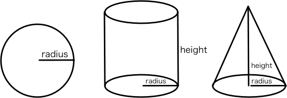
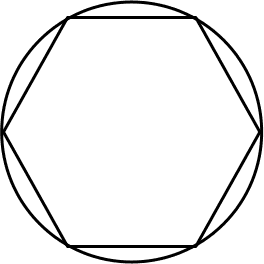
These meshes' surface is curved, G3D use line strip to simulate curve line. For example, a circle could be roughly simulated using 6 lines, or nicely simulated using 128 lines. The segs argument is used to specify how many lines should be used to simulate a circle. The larger the number is, the nicer G3D simulates (and cost more, of course).
This example demonstrated how to create sphere, cylinder and cones, with different segs arguments.
We created three cylinders, three spheres and three cones, with segs 6, 16 and 128. It's obvious that segs deeply affect how nice the curved face is simulated.
Meshes with Custom Shapes
Except for these pre-defined shaped meshes, we can alse mannually create vertices and make up our own custom shaped meshes. It's a little bit tricky, so let's begin with a simple issue: How to create custom shaped line mesh. (Spheres, cubes and so on are face meshes, but the coordinate mesh we created before is line mesh).
Line Mesh
Assume that we want to create a line strip in X-Y plane, passing through (0, 0, 0), (1, 1, 0), (1, 0, 0), (2, 1, 0), (2, 0, 0) and so on, as the following image shows:
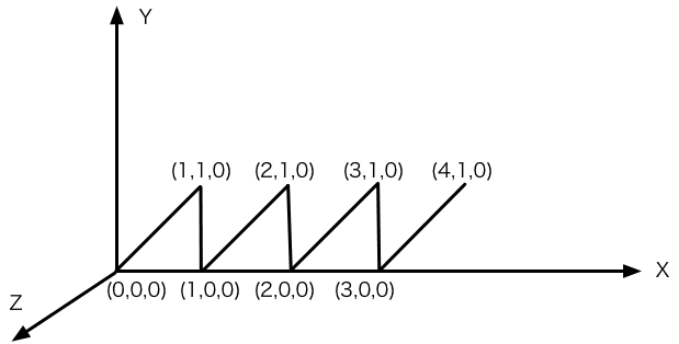
Let's see the demo:
First, create two arrays vertices and indices:
const vertices = [];
const indices = [];
for(let i=0; i<4; i++){
vertices.push(0+i, 0, 0, 1+i, 1, 0);
if(i!==0){
indices.push(i*2-1, i*2);
}
indices.push(i*2, i*2+1);
}
// vertices: [0,0,0, 1,1,0, 1,0,0, 2,1,0, 2,0,0, 3,1,0, ...]
// 0 1 2 3 4 5
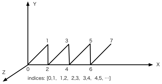
// indices: [0,1, 1,2, 2,3, 3,4, 4,5, ...]The array vertices container all vertice positions along the line strip, each three values for a vertices. The line containers 8 vertices, so the length of vertices is 24.
The array indices defines how the vertices in vertices composite a line strip. Each value in indices is an index for vertices array, corresponding with a vertice. In the example, indices is [0,1,1,2,...]. The first two value 0 and 1 means: The first line, start with the 0th vertice in vertices which is (0, 0, 0), ends with the 1st vertice which is (1, 1, 0); the following two value 1 and 2 means: the second line, start with 1st vertice which is (1, 1, 0) and ends with the 2nd vertice which is (1, 0, 0); and so on.
Then we can create a LineMesh object, and create a LineGeometry, passing vertices and indices in. Notice that we put indices in a default property, this is because a line mesh may contain multiple line strips, the first one's name is default by default.
const lines = new G3D.LineMesh(scene);
lines.geometry = new G3D.LineGeometry({
    vertices,
    indices: {
        default: indices
    }
})
So we finished creating a custom shaped line mesh.
Face Mesh
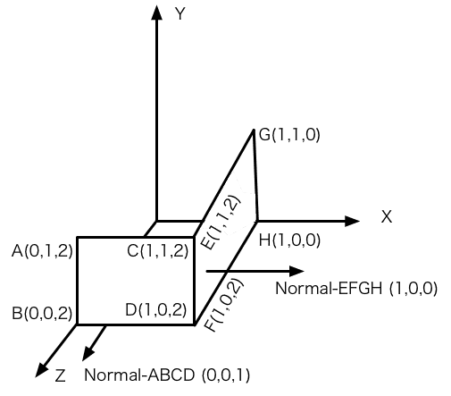
Creating face mesh is a little complecated. Assum that we want to create a face mesh composited of two rectangle planes ABCD and EFGH:
See the example:
Except for vertices and indices, we need to create uvs and normals.
const vertices = [
    0,1,2, // A
    0,0,2, // B
    1,1,2, // C
    1,0,2, // D
    1,1,2, // E
    1,0,2, // F
    1,1,0, // G
    1,0,0  // H
];
const normals = [];
const uvs = [];
for(let i=0; i<8; i++){
    if(i<=3){
        normals.push(0,0,1);
    }else{
        normals.push(1,0,0);
    }
    uvs.push(0,0);
}
The array vertices container 8 points, which is the similar to when we created line mesh before.
Normal is the vector perpendicular to the face. For line meshes, normals makes no sense, but for face meshes, normals participates in computing the light and the final render color, it's essantial. In our example, for the first four vertices, normal is (0, 0, 1), and for the 4 vertices left, normal is (1, 0, 0).
You may notice that the mesh has only 6 vertices literally, cause point C and point E is the same point, as well as D and F. C and E has the same position, but the normal is different, so we have to split it into two points.
UV is similar to normals, it's data for each vertices, but UV only need two values for one vertice. UV is related to the texture and material, as we have not involved in these issues, we can just specify (0, 0) for each vertice.
At last we created the vertice index array indices. For line geometry, the rule is "each two indices make up a line segment", and here for face geometry, the rule is "each three indices make up a triangle". Face meshes are composited with triangles, so rectangle plane should be split into two triangles. Here in the example, indices demonstrate 4 triangles, they are triangle ABC and BDC (which composite rectangle ABCD), and triangle EFH and HGE (which composite rectangle EFGH).
const indices = [
    0,1,2, // triangle ABC
    1,3,2, // triangle BDC
    4,5,7, // triangle EFH
    7,6,4  // triangle HGE
]
At last, create a Mesh. We used LineMeshed and LineGeometry before, here we need Mesh and Geometry. For the same reason, indices is in the default property.
const mesh = new G3D.Mesh(scene);
mesh.geometry = new G3D.Geometry({
    vertices,
    normals,
    uvs,
    indices: {
        default: indices
    }
});
Please drag your mouse in the right rendering canvas, to rotate the camera to the backside of our mesh (or you can edit code to change the camera, camera.alpha = 200). You find that when camera looks at the mesh from back side, the mesh is gone! (This won't happen for the mesh you created from MeshBuilder.createPlane()).
This is because, mostly face mesh is closed, you are not supposed to see the back side of a plane. For better performance, we'll not render the back side. In G3D, Geometry has a 'facing', when creating Geometry, you can specify a facing property as Geometry.FACING.FRONT (the default value),Geometry.FACING.BACK or Geometry.FACING.BOTH.
So if we want the mesh to be seen from both side, then specify BOTH as following code shows:
mesh.geometry = new G3D.Geometry({
    ...
    facing: G3D.Geometry.FACING.BOTH
})
How to recognize the front side and back side? Here we use the Right Hand Rule again. Use your right hand, make the four fingers rotate along the triangle vertices in order (A->B->C, eg), then the thumb is pointing at the front side.
Summary
In this section we learned: 1) How to create pre-defined shaped meshes using MeshBuilder. 2) How to create custom shaped meshes. Hope the artical is helpful.